 Free JavaScript Editor
Ajax Editor
12.1. Hemisphere LightingIn Chapter 9, we looked carefully at the fixed functionality lighting model built into OpenGL and developed shader code to mimic the fixed functionality behavior. However, this model has a number of flaws, and these flaws become more apparent as we strive for more realistic rendering effects. One problem is that objects in a scene do not typically receive all their illumination from a small number of specific light sources. Interreflections between objects often have noticeable and important contributions to objects in the scene. The traditional computer graphics illumination model attempts to account for this phenomena through an ambient light term. However, this ambient light term is usually applied equally across an object or an entire scene. The result is a flat and unrealistic look for areas of the scene that are not affected by direct illumination. Another problem with the traditional illumination model is that light sources in real scenes are not point lights or even spotlightsthey are area lights. Consider the indirect light coming in from the window and illuminating the floor and the long fluorescent light bulbs behind a rectangular translucent panel. For an even more common case, consider the illumination outdoors on a cloudy day. In this case, the entire visible hemisphere is acting like an area light source. In several presentations and tutorials, Chas Boyd, Dan Baker, and Philip Taylor of Microsoft described this situation as HEMISPHERE LIGHTING and discussed how to implement it in DirectX. Let's look at how we might create an OpenGL shader to simulate this type of lighting environment. The idea behind hemisphere lighting is that we model the illumination as two hemispheres. The upper hemisphere represents the sky, and the lower hemisphere represents the ground. A location on an object with a surface normal that points straight up gets all of its illumination from the upper hemisphere, and a location with a surface normal pointing straight down gets all of its illumination from the lower hemisphere (see Figure 12.1). By picking appropriate colors for the two hemispheres, we can make the sphere look as though locations with normals pointing up are illuminated and those with surface normals pointing down are in shadow. Figure 12.1. A sphere illuminated using the hemisphere lighting model. A point on the top of the sphere (the black "x") receives illumination only from the upper hemisphere (i.e., the sky color). A point on the bottom of the sphere (the white "x") receives illumination only from the lower hemisphere (i.e., the ground color). A point right on the equator would receive half of its illumination from the upper hemisphere and half from the lower hemisphere (e.g., 50% sky color and 50% ground color).
To compute the illumination at any point on the surface, we must compute the integral of the illumination received at that point:
where
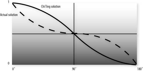
But we can actually calculate a in another way that is simpler but roughly equivalent:
This approach eliminates the need for a conditional. Furthermore, we can easily compute the cosine of the angle between two unit vectors by taking the dot product of the two vectors. This is an example of what Jim Blinn likes to call "the ancient Chinese art of chi ting." In computer graphics, if it looks good enough, it is good enough. It doesn't really matter whether your calculations are physically correct or a colossal cheat. The difference between the two functions is shown in Figure 12.2. The shape of the two curves is similar. One is the mirror of the other, but the area under the curves is the same. This general equivalency is good enough for the effect we're after, and the shader is simpler and will likely execute faster as well. Figure 12.2. Comparing the actual analytic function for hemisphere lighting to a similar but higher-performance function.
For the hemisphere shader, we need to pass in uniform variables for the sky color and the ground color. We can also consider the "north pole" to be our light position. If we pass this in as a uniform variable, we can light the model from different directions. Listing 12.1 shows a vertex shader that implements hemisphere lighting. As you can see, the shader is quite simple. The main purpose of the shader is to compute the diffuse color value and pass it on to fixed functionality fragment processing so that it can be written into the framebuffer. We accomplish this purpose by storing the computed color value in the built-in varying variable gl_FrontColor. Results for this shader are shown in Color Plate 21D and G. Compare this to the results of shading with a single directional light source shown in Color Plate 21A and B. Not only is the hemisphere shader simpler and more efficient, it produces a much more realistic lighting effect too! This lighting model can be utilized for tasks like model preview, where it is important to examine all the details of a model. It can also be used in conjunction with the traditional computer graphics illumination model. Point, directional, or spot lights can be added on top of the hemisphere lighting model to provide more illumination to important parts of the scene. Listing 12.1. Vertex shader for hemisphere lighting
One of the issues with this model is that it doesn't account for self-occlusion. Regions that should really be in shadow because of the geometry of the model appear too bright. We remedy this in Chapter 13. |
 Ajax Editor
JavaScript Editor